P s if we can g.
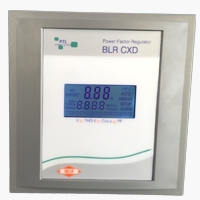
Power factor relay function.
Power factor relay user friendly and fully intuitive installation computer max provides the phase selection function that allows the user choosing the power line phase where the measuring current transformer c t has been placed in.
They are used in many applications like used for the purpose of controlling a circuit by a low power signal.
These relays are best in functionality and easy to use.
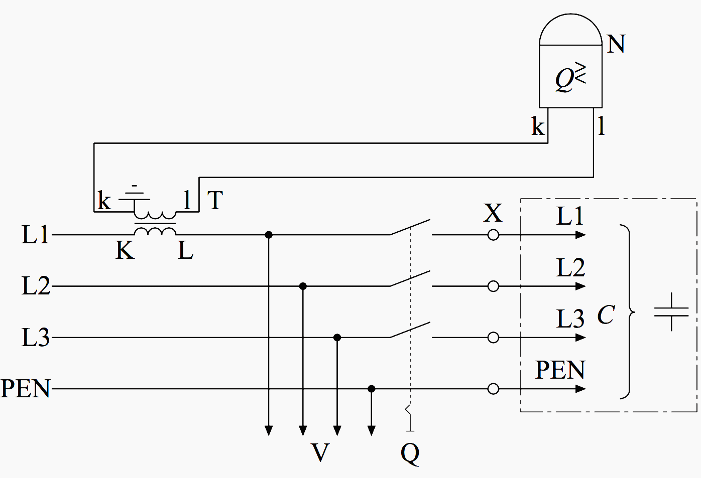
In the design of electrical power systems the ansi standard device numbers ansi ieee standard c37 2 standard for electrical power system device function numbers acronyms and contact designations identifies the features of a protective device such as a relay or circuit breaker these types of devices protect electrical systems and components from damage when an unwanted event occurs such.
These electrical relays are designed and created by our professionals with best tools.
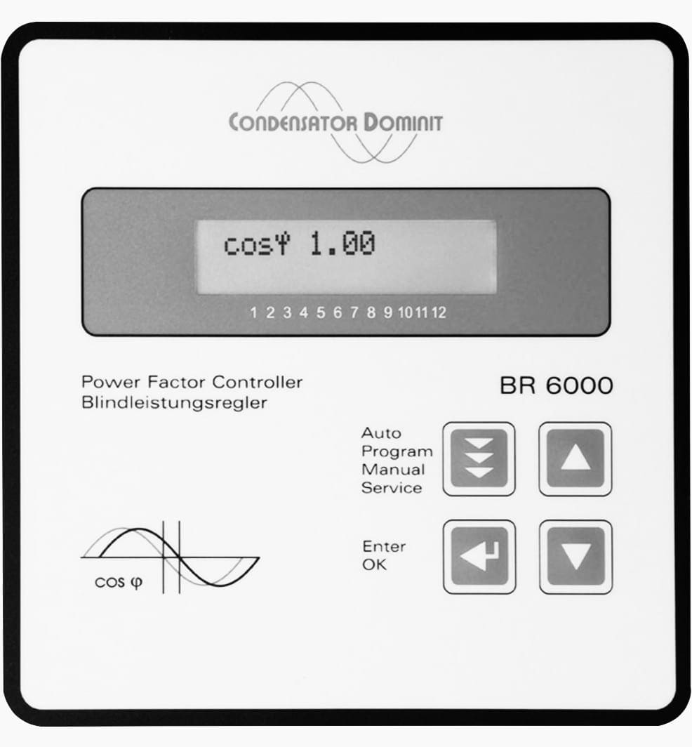
The hitachi abb power grids rvc retains all its widely accepted functionalities and continue to deliver an easy to install easy to use and smarter power factor controller to the market.
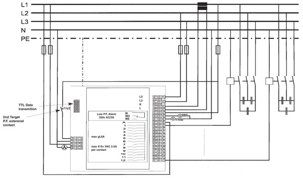
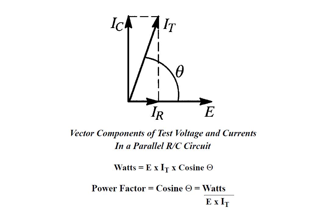
An automatic power factor correction unit consists of a number of capacitors that are switched by means of contactors these contactors are controlled by a regulator that measures power factor in an electrical network.
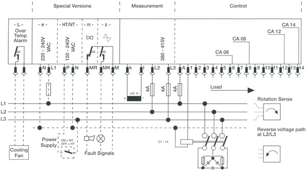
Applications the rvc standard range of controllers can be used to control cos φ in industrial and commercial networks.
The range of relays has patented control attributes along with over current trip function and protection for the capacitors.
Tc stands for trip coil a refers to a.
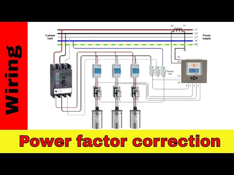
In this video you will see how to wire power factor relay and power capacitors to create a complete power factor correction panel.
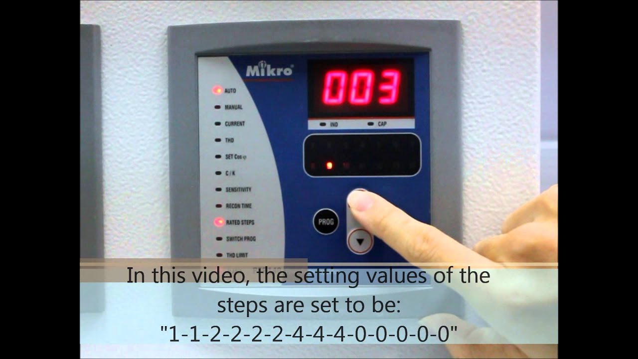
Depending on the load and power factor of the network the power factor controller will switch the necessary blocks of capacitors in steps to make sure the power factor stays.
Fully automatic microprocessor based and easy commissioning this power factor control relays are offered in a variety of rm9606 rm2106 emr1100s rm 2112 rm 2012.
Relays are normally used in the control panels manufacturing and building automation to control the power along with switching the smaller current values in a control circuit.
52 refers to the power circuit breaker 51 refers to the time overcurrent function dashed numbers specify which relay out of the three relay set one electromechanical overcurrent relay assembly per phase and letters found below the horizontal line identify elements of the component s function e g.
This option eliminates the difficulty in placing the c t.
Visit our website here and you will get right product as per your requirement.
However the supply of amplifying effect can help control the large amperes and voltages because if low voltage is applied to the relay coil a large voltage can be switched by the contacts.
We are offering automatic power factor relay.